Utility vs. Design Patent Drawings
Utility and design patent drawings serve different purposes, follow different rules, and require entirely different skill sets. Understanding these differences is essential for anyone preparing drawings or supervising patent drafting work. This chapter explains the functional and legal distinctions between the two drawing types, as well as the practical skill requirements for producing them correctly.
What Utility Patent Drawings Aim to Show
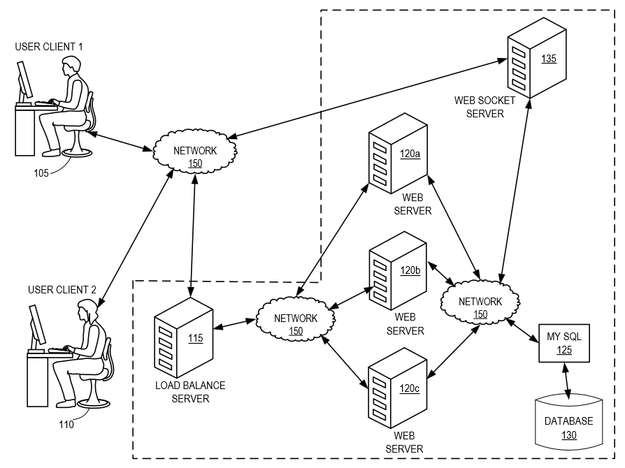
Figure 2.1 — Typical utility drawing categories such as flowcharts, system diagrams, and GUI figures.
Utility patents protect how an invention works, its structure, function, methods, systems, and interactions. Because the purpose is functional, the drawings must clearly illustrate:
- components
- relationships
- flow of information
- structural connections
- user interfaces
- processes and algorithms
- system architectures
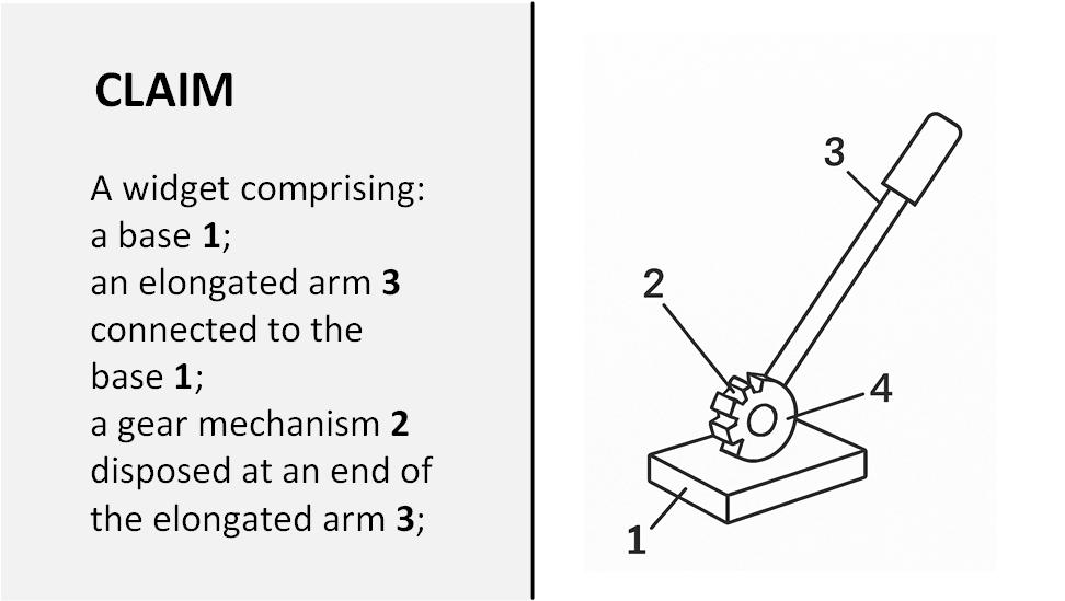
Figure 2.2 — Correspondence Between Claim Elements and Drawing References.
Utility figures support a detailed written specification and claims drafted by a patent attorney. The drawings visually reference elements that appear in the specification through:
- reference numbers
- lead lines
- figure labels
These references are essential for clarity and to avoid ambiguity. Every element mentioned in the text must appear in the figures, and every referenced element in the figures must be explained in the specification.
Skill Requirements for Utility Drawings
Most utility drawing types do not require special artistic, CAD, or technical training. Using tools like Microsoft Visio and the IP DaVinci Toolkit, beginners can quickly learn to produce professional, compliant drawings, even with zero prior experience.
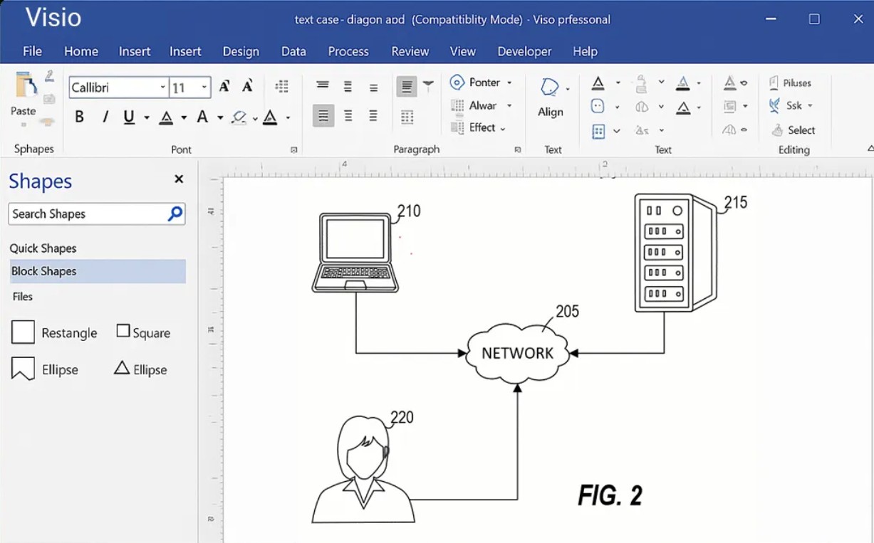
Figure 2.3 — Utility diagrams can be created quickly using drag-and-drop Visio stencils.
Common utility drawing types include:
- flowcharts
- system and network diagrams
- block diagrams
- GUI screenshots
- tables and data structures
- graphs
- simple image tracings
- basic mechanical outlines
With standardized stencils, templates, and drag-and-drop shapes, these drawings are fast, repeatable, and accessible to anyone willing to follow a structured method.
What Design Patent Drawings Aim to Show
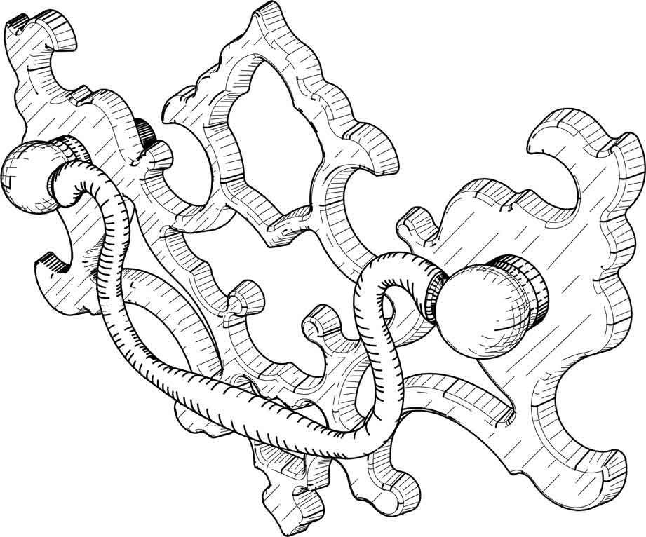
Figure 2.4 — Design drawings rely on precise multi-view geometry and shading.
Design patents protect how an article looks, not how it works. Because design protection covers ornamental appearance, the drawings must show:
- every visible contour
- proportions
- curvature
- shading
- surface transitions
- edge definition
- perspective and orientation
The drawings are the entire legal definition of the design. Unlike utility patents, the written description in a design patent is extremely short—usually only a few sentences. The figures themselves define the scope of the patent.
Skill Requirements for Design Drawings
Design patent drawings require a level of precision and artistic/technical skill that most illustrators and even many experienced utility drafters do not possess.
Key reasons include:
- Shading must be consistent and uniform.
- Line weight must be precise and meaningful.
- Contours must accurately represent 3D geometry.
- Even minor mistakes can introduce new matter during correction, making amendments difficult or impossible.
- Figures must align perfectly across views (front, rear, left, right, top, bottom, perspective).
- Small discrepancies can weaken or invalidate the protection.
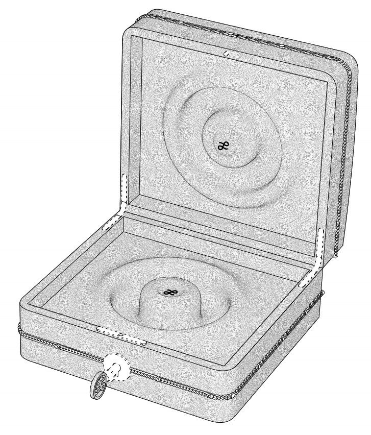
Figure 2.5 — Design patent shading must accurately represent curvature and surface transitions.
For these reasons, design drawings should be prepared by specialists—not general patent drafters, not utility-focused illustrators, and not in-house staff without design-specific experience.
Design drawings must be perfect the first time, because post-filing corrections are limited and risky.
Reference Numbers: A Key Difference
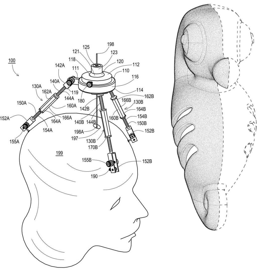
Figure 2.7 — Utility drawings use reference numbers; design drawings do not.
The use (or non-use) of reference numbers is a simple but important structural difference.
Utility Drawings
✔ Use reference numbers and lead lines
✔ Tie visual elements to the written specification
✔ Help describe how the invention works
Design Drawings
✘ Do not use reference numbers
✘ Do not include lead lines
✘ Do not label elements in the figures
Design drawings must speak for themselves. References, labels, shading inconsistencies, or unnecessary markings can introduce ambiguity or even limit scope unintentionally.
Summary of Differences
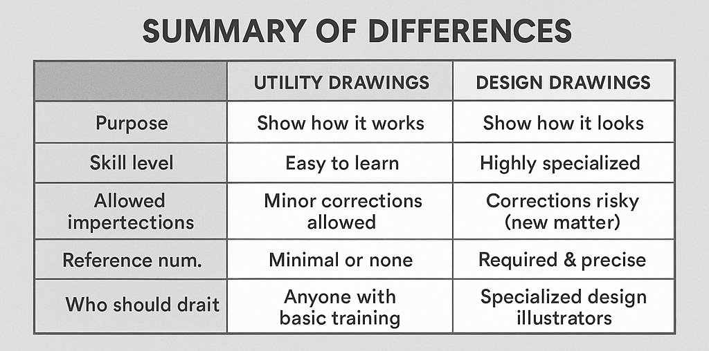
Figure 2.8 — Summary comparison of utility and design drawing characteristics.
| Feature | Utility Drawings | Design Drawings |
|---|---|---|
| Purpose | Show how it works | Show how it looks |
| Skill level | Easy to learn with Visio + Toolkit | Highly specialized |
| Allowed imperfections | Minor corrections allowed | Corrections risky (new matter) |
| Reference numbers | Required | Not allowed |
| Shading | Minimal or none | Required & precise |
| File preparation | Diagrams, screenshots, tracings | Perfect multi-view geometry |
| Who should draft | Anyone with basic training | Specialized design illustrators |
Practical Guidelines
- Utility drawings can be created quickly by trained assistants, students, engineers, or non-technical staff using Visio and IP DaVinci templates.
- Design drawings should always be delegated to qualified vendors with proven experience in design-specific illustration.
- Never assume a utility drawing specialist can produce design drawings—they are fundamentally different disciplines.
A strong understanding of these differences helps ensure that each type of patent filing is supported by the correct level of detail, clarity, and professional skill.