Utility Patent Drawing Techniques
Utility patent drawings can be created using a variety of techniques depending on the complexity of the invention, the available source materials, and the level of detail required. This chapter divides the most common techniques into Basic and Advanced, offering guidance on when and how each method should be used.
Basic Utility Patent Drawing Techniques
1. Photographs in Lieu of Drawings
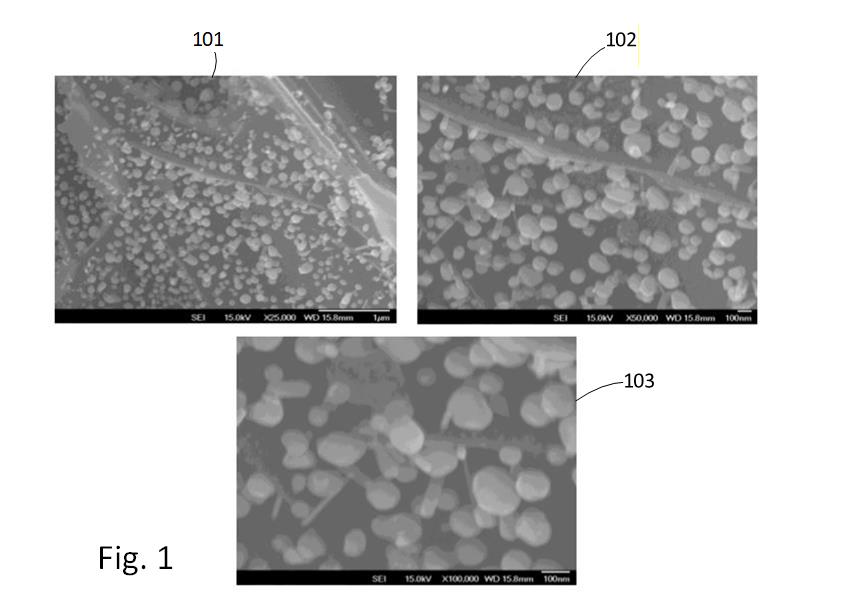
Figure 4.1 — Example of a high-resolution photograph used when a line drawing cannot accurately capture fine detail (e.g., microscopic structures or complex textures).
In certain situations, a photograph is the most accurate and legally appropriate way to depict an invention—especially when a traditional line drawing cannot properly convey the essential features. Examples include:
- microscopic subjects
- complex biological structures
- materials with fine patterns or gradients
- surfaces or textures that cannot be captured with line art
In these cases, the USPTO permits photographs if they are the only practical method of illustrating the invention.
Recommended workflow (Visio-based):
- Insert the original photo into Visio.
- Adjust brightness, contrast, and sharpness to increase clarity.
- Crop the image to isolate only the relevant region.
- Convert to grayscale unless color is essential to the invention.
- Add reference numbers, lead lines, and figure labels.
- Ensure the image resolution is sufficiently high to withstand printing and PDF conversion.
This approach preserves the integrity of the subject while keeping the figure fully compliant with utility drawing standards.
2. Image Tracing (Line-Art Conversion)
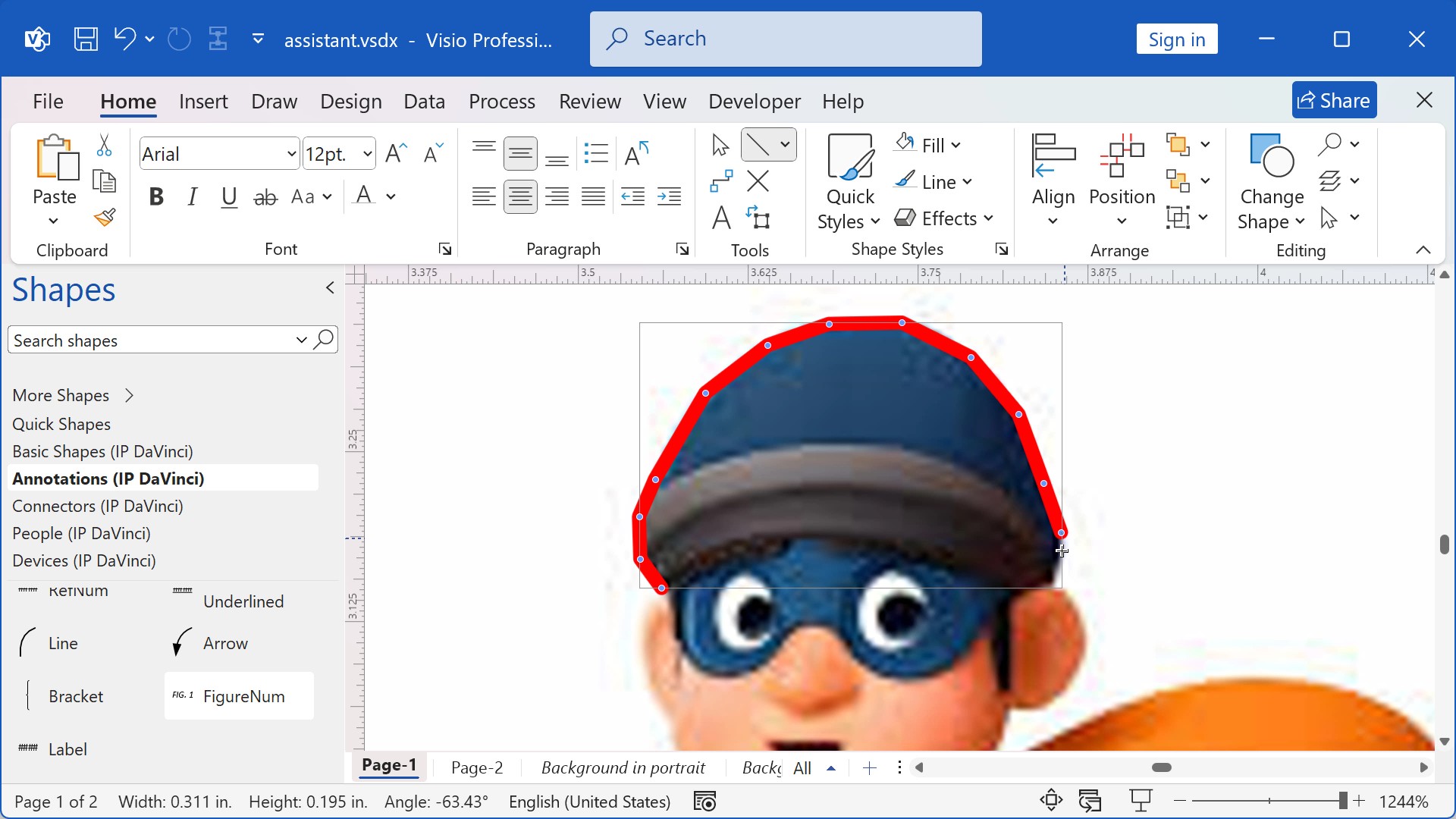
Figure 4.3 — Example of using red tracing lines over a locked background image to create accurate line art.
Tracing is used when you need to convert a real-world object, product, machine, or device into clean, black-and-white line art. This technique is common when creating:
- system diagrams with realistic components
- instrumentation and medical device figures
- mechanical components
- structural elements of devices shown in partial or exploded views
Typical workflow:
- Insert the source image onto its own layer.
- Lock the image layer to prevent accidental movement.
- Activate a tracing layer, often using red lines to distinguish new work from the background.
- Trace only the essential contours and features needed for understanding the invention.
- Replace tracing strokes with proper line weights and cleanup.
- Remove or hide the original image layer to reveal the finished line drawing.
This process creates clear, professional, and patent-office-compliant line art while maintaining accuracy to the original image.
3. Drag-and-Drop (Stencil-Based Drawing)
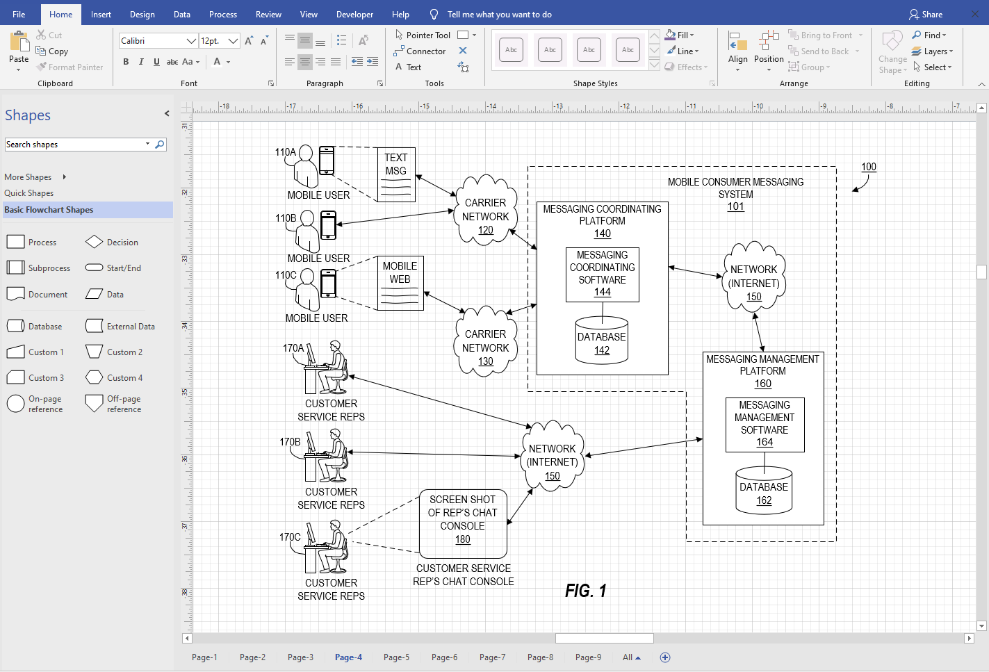
Figure 4.6 — Visio stencil example showing reusable blocks, connectors, and interface shapes used for utility diagrams.
Many utility patent drawings—particularly flowcharts, block diagrams, GUI layouts, and system diagrams—are best created by reusing standardized shapes. Visio’s stencil system makes this extremely efficient.
Users can:
- drag shapes from stencils onto the page
- resize and position them
- connect elements with standardized connectors
- maintain consistency across dozens of figures
This technique is ideal for:
- flowcharts
- system and network diagrams
- software architecture diagrams
- logical diagrams
- control system block diagrams
In practice, this method functions like building with LEGO® pieces: shapes are pre-designed, standardized, and optimized for clarity, allowing anyone—regardless of drawing experience—to construct compliant patent drawings rapidly.
Advanced Utility Patent Drawing Techniques
1. 3D Model–Based Drafting
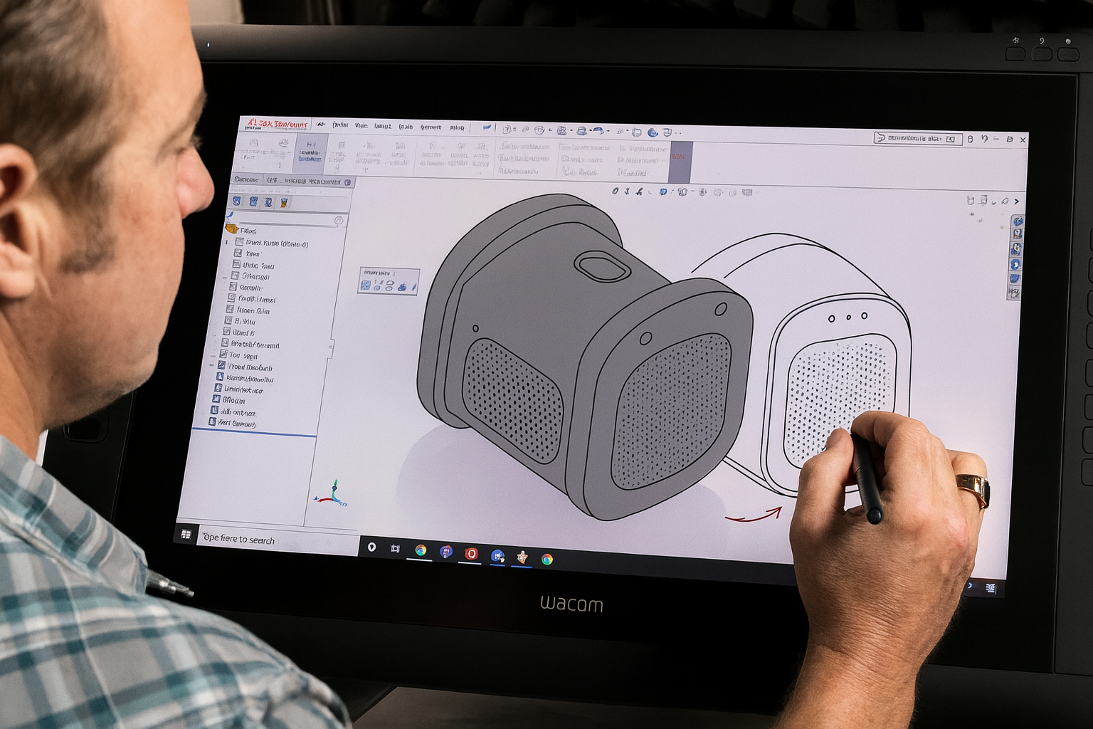
Figure 4.7 — Example of a CAD-based 3D model used to generate precise 2D patent drawing views.
When an invention has complex geometry, precise mechanical relationships, or spatial features that must be shown from multiple angles, 3D modeling provides superior accuracy.
A typical workflow:
- Create or receive a 3D model of the invention.
- Generate orthographic or isometric 2D views (front, side, perspective, cross-section, etc.).
- Export these views as vector or high-resolution raster files.
- Insert them into Visio for final cleanup and annotation.
This method allows precise depiction of mechanical structures and is particularly effective for:
- mechanical assemblies
- consumer products
- medical devices
- industrial machinery
- geometrically complex inventions
Using 3D models minimizes distortion, preserves proportions, and ensures consistency across all figures.
2. Reusing Existing 2D/3D CAD Files
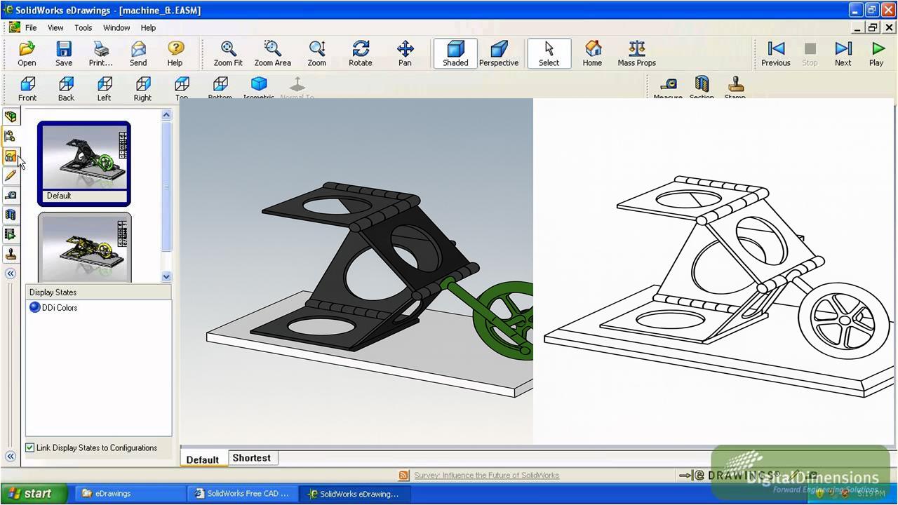
Figure 4.9 — Example of using a neutral CAD viewer to open STEP/IGES files when original CAD software is unavailable.
Inventors, engineering teams, and manufacturers often provide:
- STEP files
- IGES files
- DWG/DXF
- SolidWorks, Creo, Fusion, or CATIA exports
However, these files are not always directly usable in Visio. In many cases, the original CAD software is unavailable.
The solution is to use industry-standard CAD viewers—such as Autodesk Viewer, eDrawings Viewer, or other neutral viewers—to:
- Open the original CAD file.
- Generate high-resolution black-and-white line images (PNG, TIFF, SVG).
- Export specific views (front, perspective, sections).
- Import those images into Visio.
- Finalize formatting, annotations, and reference numbers.
High-resolution raster line drawings are often sufficient for utility drawings because patent offices primarily require clarity, not vector purity.
This technique dramatically reduces production time and consistently preserves the accuracy of the original engineering files.
Summary
Together, these techniques provide a flexible toolkit for producing professional, compliant utility patent drawings. Basic techniques handle the majority of everyday figures, while advanced methods support complex mechanical or engineered inventions. In practice, patent illustrators often combine methods—tracing photos, reusing CAD exports, dragging reusable symbols, and assembling multi-view figures—to produce clear and legally robust drawings.