Figure Standards
Figures are the heart of a utility patent application. They show how an invention works, how parts relate, how components assemble, and how processes operate. To comply with USPTO and PCT standards, figures must be prepared, arranged, labeled, and illustrated consistently using approved view types, spacing, numbering, and conventions. This chapter consolidates all requirements relating to figure layout, types of views, movement, expanded views, and specialized diagrams.
1. Orientation of Figures
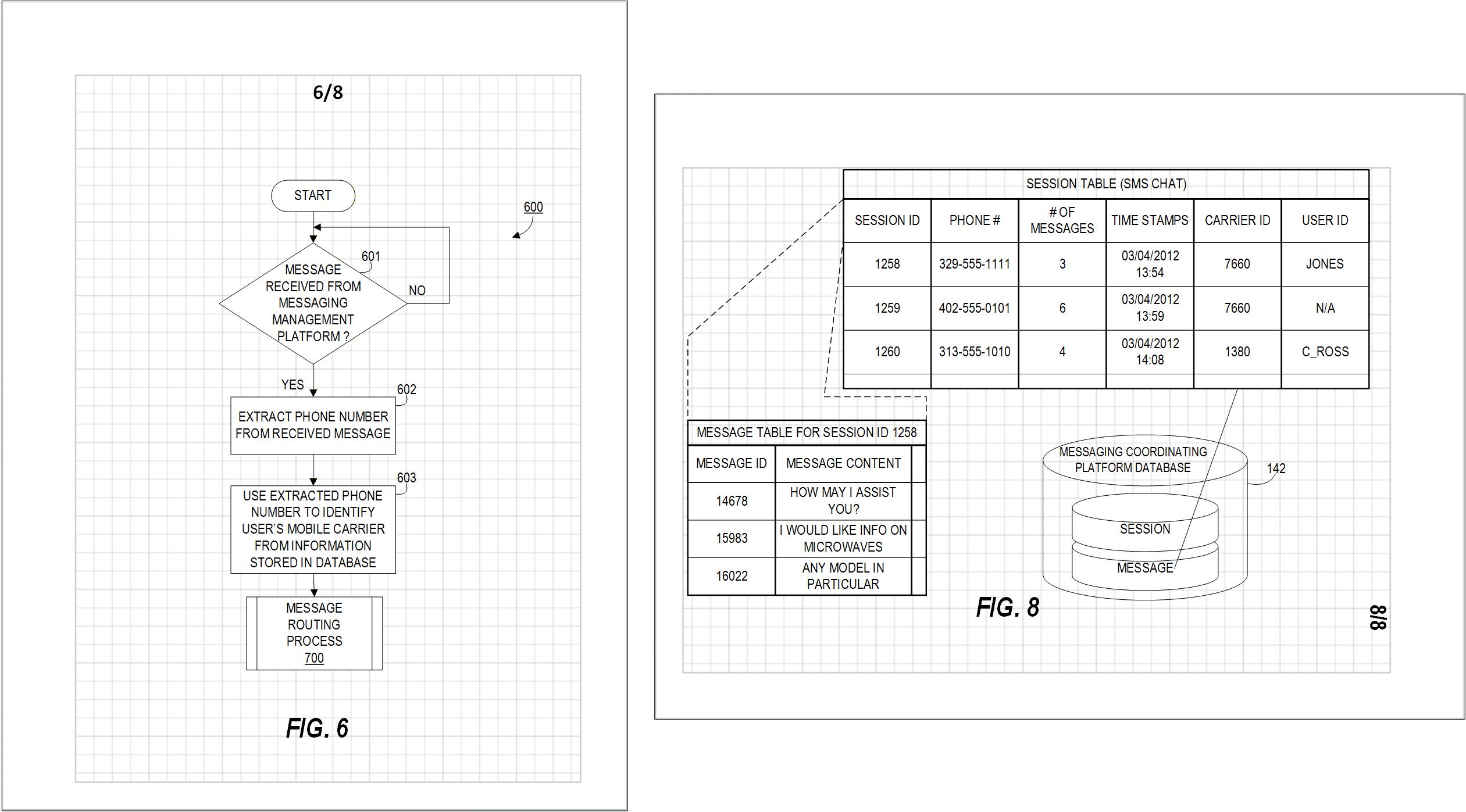
Figure 6.1 — Figures must be upright relative to the top of the sheet.
- Figures must appear upright relative to the top of the sheet.
- On landscape sheets, sheet numbers remain in portrait orientation, but figures, labels, and reference numerals rotate with the sheet.
2. Spacing Between Figures
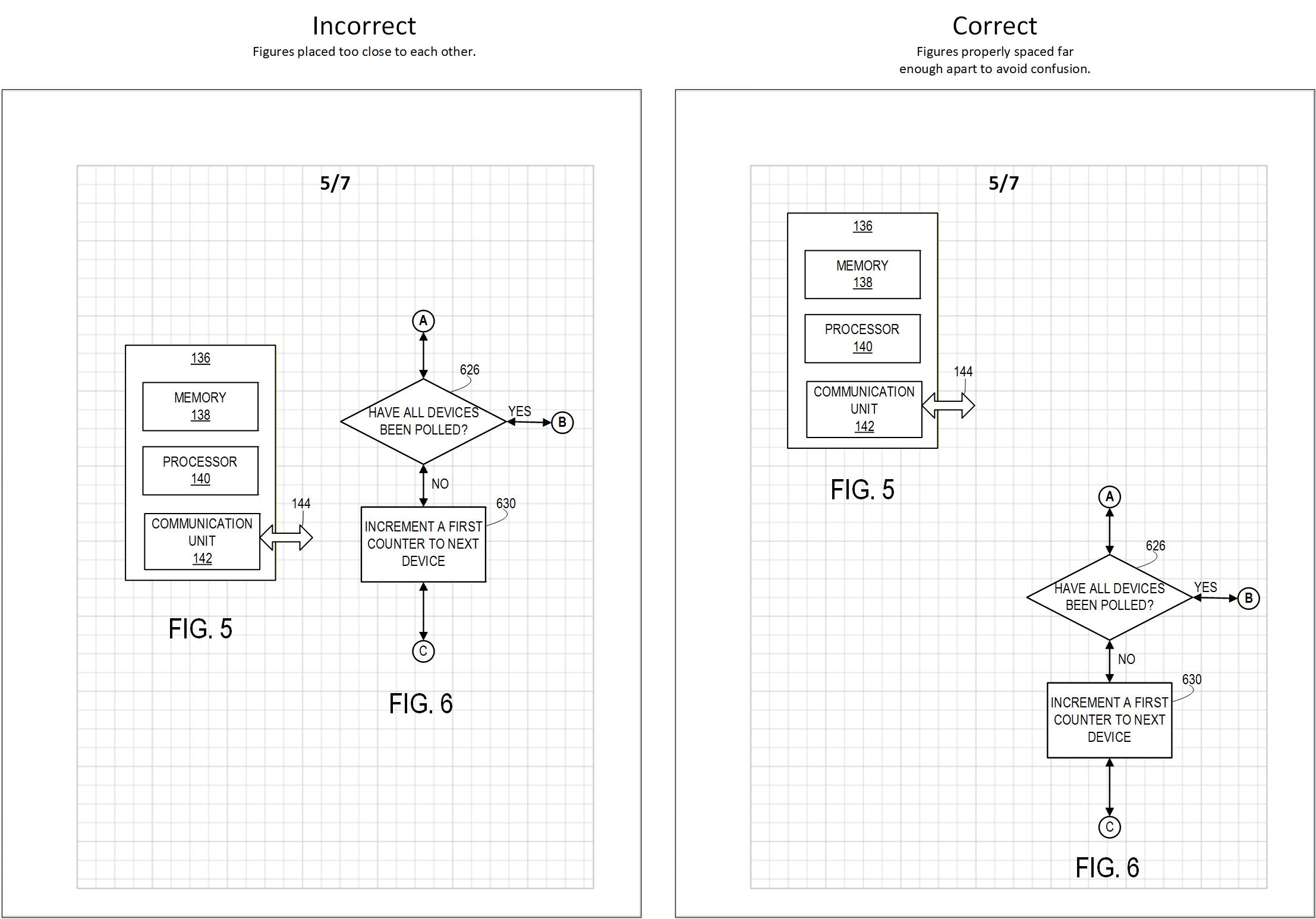
Figure 6.2 — Figures must be clearly separated. Left: figures placed too close to each other. Right: figures properly spaced.
- Figures must be spaced far enough apart to avoid confusion.
- No lines from one figure may appear to belong to another.
3. Shared Lines Between Figures
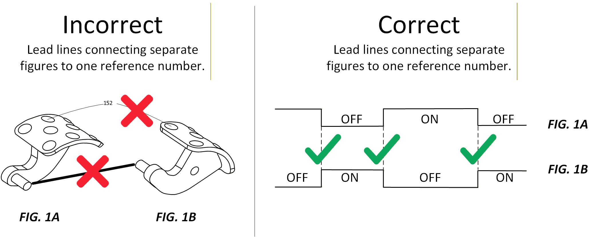
Figure 6.3 — Rules for shared lines between figures. Left: improper sharing of lines between separate figures. Right: allowable shared baseline for waveform figures.
- Figures must not be connected by construction or projection lines, except for electrical waveforms (timing relationships only).
4. Figure Size — “Bigger Is Clearer”
Figure 6.4 — Figures should be as large as possible within the margins.
Use the available space inside margins to maximize clarity:
- Avoid small figures with crowded details.
- Maximize height/width within margins.
- Legibility always takes priority.
5. Ordering of Figures
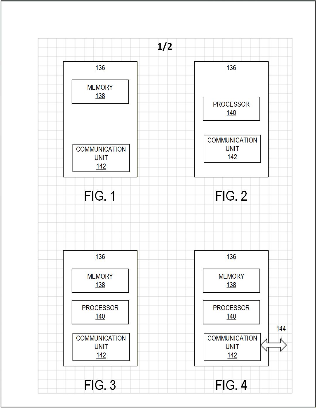
Figure 6.5 — Figures arranged left-to-right, top-to-bottom.
Rules:
- Figures advance left to right, top to bottom.
- Lower figure numbers appear on earlier sheets.
- Figure numbers continue across sheets (do not restart at FIG. 1).
6. Figure Numbering
- Use consecutive Arabic numerals.
- Prefix each with “FIG.” or “Fig.”
- Each figure number represents one figure only.
- Letter suffixes (FIG. 3A, FIG. 3B) are reserved for partial views.
- Use a simple, readable font at least 3.2 mm (⅛") or ~11 pt high.
PART II: TYPES OF VIEWS
Understanding different types of views is essential for properly representing mechanical, electrical, and process-based inventions.
7. Orthogonal Views (Engineering Views)
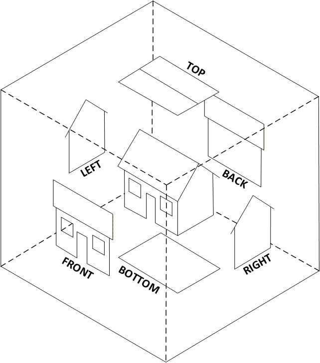
Figure 6.7 — Orthogonal views show the invention from fixed directions.
Orthogonal views include:
- front
- rear
- left
- right
- top
- bottom
They are precise but sometimes harder for non-experts to interpret.
8. Perspective Views
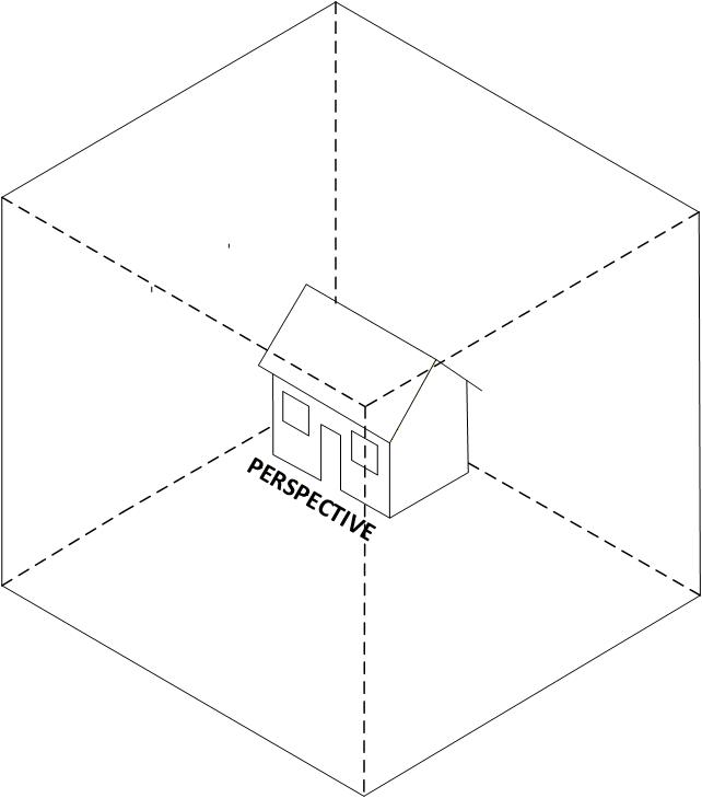
Figure 6.8 — Perspective view used to give overall understanding.
Perspective views:
- are easier to understand
- show shape and spatial relationships
- are often ideal as FIG. 1
Use additional perspectives if one view cannot show all important features.
9. Exploded Views
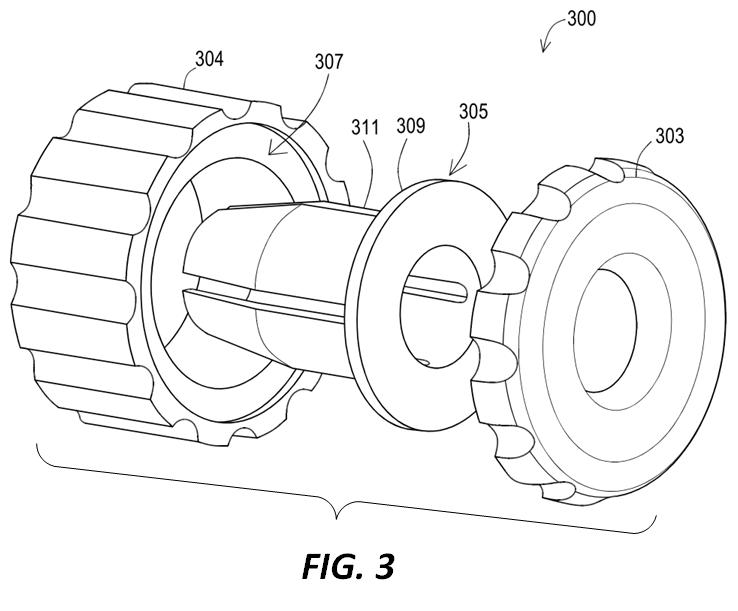
Figure 6.9 — Exploded view showing separated components.
Use exploded views to show how parts assemble.
Rules:
- Separate each part far enough to reveal essential details.
- Orientation should be perpendicular to assembled position unless clarity requires otherwise.
- Brackets must group disconnected parts—unless the exploded view is the only figure on the sheet.
- Projection lines may show how parts align (dot-dash lines).
10. Partial Views (When a Figure Is Too Large)
When a figure is too large to fit clearly on a single sheet, the USPTO allows partial views so that the invention can still be shown at usable scale.
Use partial views when:
- the invention is too long or wide to fit on one sheet, or
- details become too small when the entire object is reduced.
Two main methods are available:
- On-page continuation symbols (for diagrams).
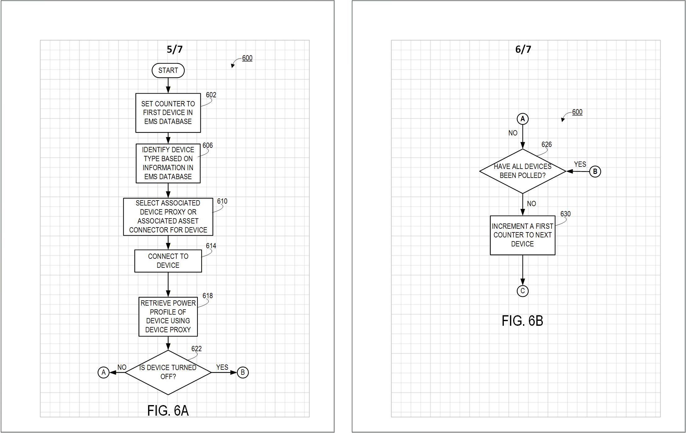
Figure 6.10 — Partial views extended across multiple sheets.
- For flowcharts, block diagrams, logic diagrams, and system diagrams, use labeled connectors (A, B, C…) at the edge of the sheet.
- Place matching “FROM A”, “TO B”, etc., at the start of the continuation on the next sheet.
- Arrows may be used to indicate the direction of the flow.
- Tiled partial views (for physical objects).
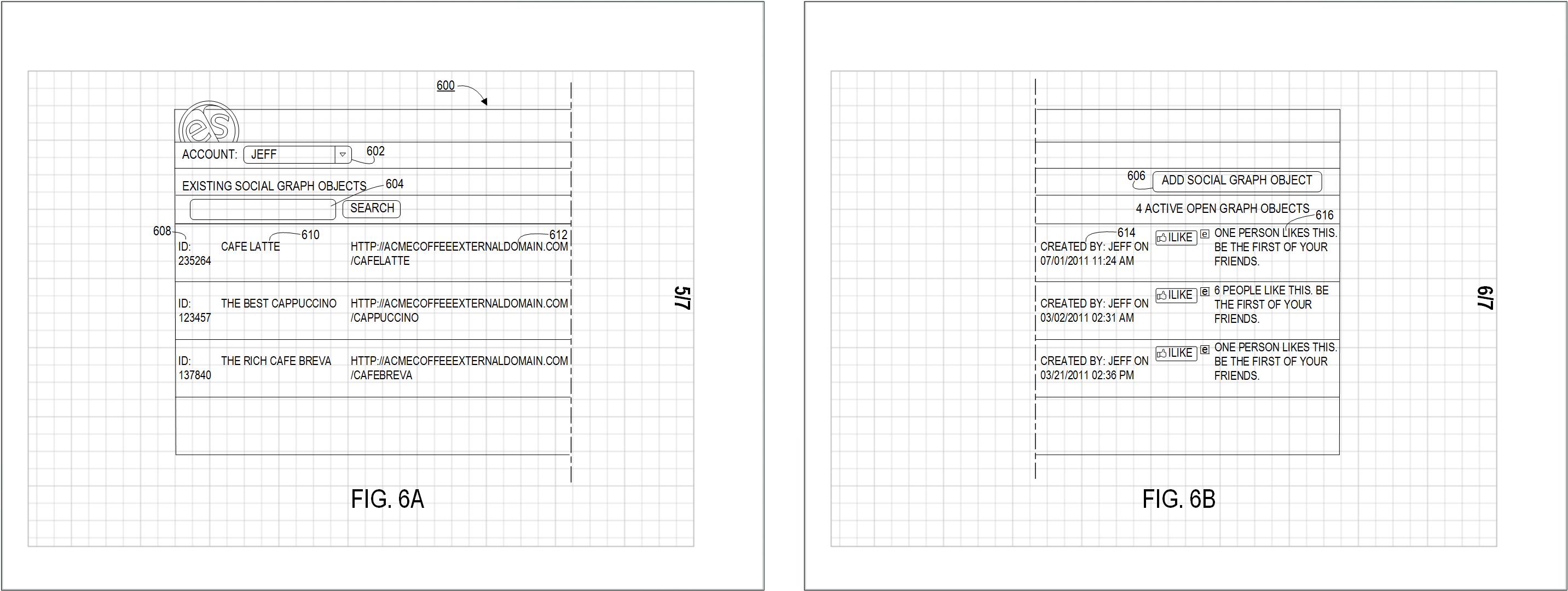
Figure 6.10 — Partial views extended across multiple sheets.
- For mechanical and pictorial views, divide the object into partial views that can be tiled together like bathroom tiles.
- Place each partial view on its own sheet and label them with lettered suffixes (FIG. 3A, FIG. 3B, FIG. 3C, etc.).
- Use dot–dot–dash (phantom) lines along the broken edges to show where the figure continues.
- Arrange the sheets so the full figure can be reconstructed without overlap or ambiguity (side-by-side, top-to-bottom, or in a rectangular array).
For very long, uniform parts where the middle contains no important detail, it is often better to shorten the figure using break symbols instead of tiling across multiple sheets (see Section 10).
11. Shortened Figures (Break Symbols)
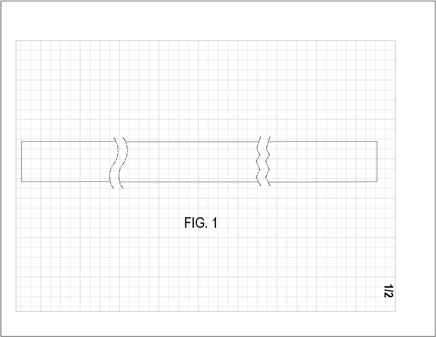
Figure 6.11 — Two Ways to shorten a long object.
To show a long object:
- remove a central section
- add break indicators (zig-zag phantom line)
- ensure no essential details are removed
12. Sectional Views (Cutaway)
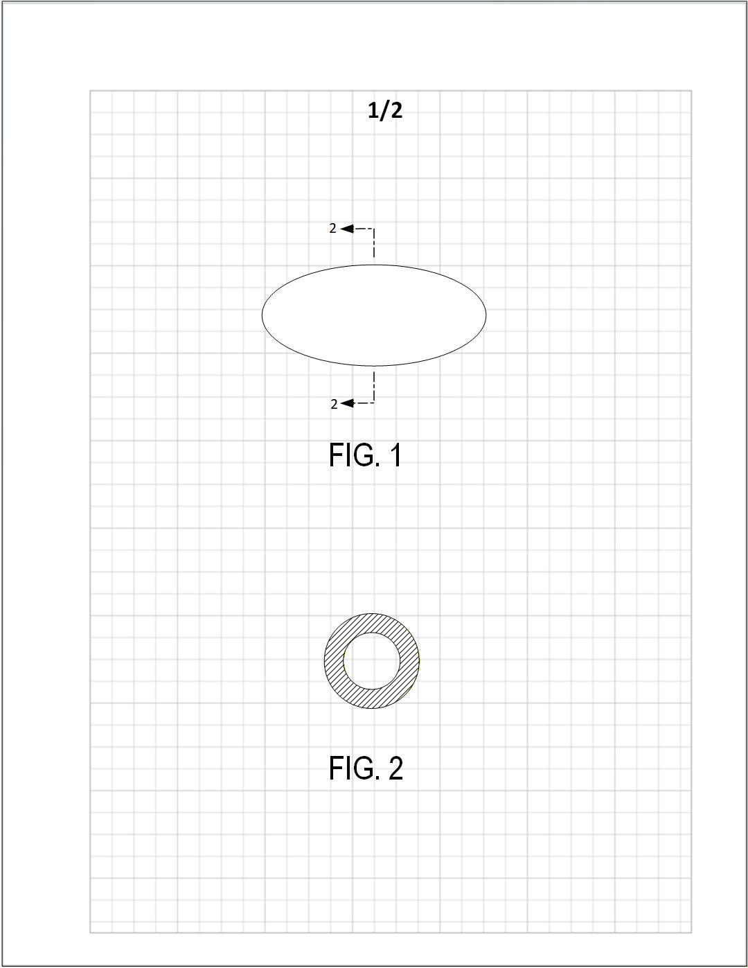
Figure 6.12 — Broken line and arrows indicate the section plane.
To reveal hidden parts:
- In the general view, draw a broken line across the object to show the cutting plane.
- Place arrows at the ends of the cutting plane to indicate the direction of sight.
- Write the section figure number next to each arrow (for example, “2” for FIG. 2, or “2–2” depending on style) so it is clear which figure shows the section.
- In the sectional view, hatch the exposed cut surfaces (45° recommended) to distinguish them from uncut surfaces.
13. Moving Parts
13.1 Arrows Indicating Movement
Figure 6.13 — Use arrows to indicate rotation or sliding.
Simple movement may be shown using:
- straight arrows for linear motion
- curved arrows for rotation
13.2 Phantom Lines for Moved Positions
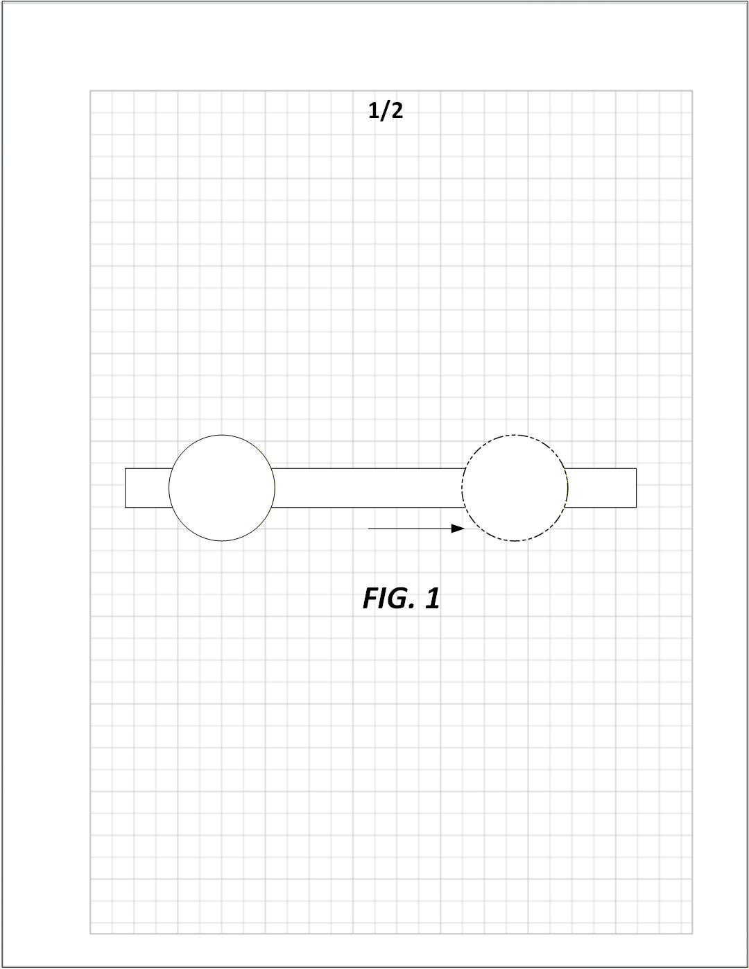
Figure 6.13 — Phantom (dot–dot–dash) lines show alternate positions.
Use phantom lines when:
- the moved position must appear in the same figure
- no confusion will result
13.3 Separate Figures for Movement
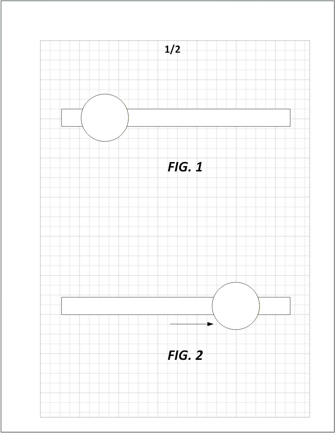
Figure 6.13 — Initial and moved positions shown in different figures.
Use separate figures to show clearer movement steps.
Optional arrows may be included.
Use multiple figures to illustrate:
- multi-step sequential mechanical operations
- multi-stage actuators
- multi-state valves
- mechanisms with multiple interactions
14. Enlarged Views
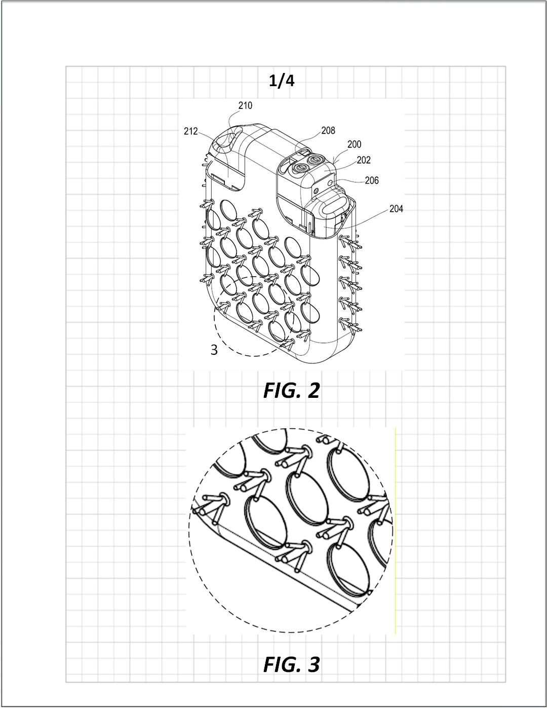
Figure 6.14 — Enlarged views use a dashed circle to highlight the region being magnified.
Enlarged views are used when a portion of a device contains details that cannot be shown clearly at the scale of the general view.
Rules:
- Surround the detailed region in the main figure with a dashed circle (or irregular dashed boundary if needed).
- Apply a reference number to the dashed circle indicating which figure shows the enlargement
(e.g., the circle labeled “8” corresponds to FIG. 8). - In the enlarged figure, repeat the dashed boundary around the enlarged portion so the correspondence is clear.
- The enlarged view must include all reference numerals necessary to understand the details.
- Enlargements should be large enough to show fine structure without overcrowding.
Enlarged views are especially useful for:
- intricate mechanical joints
- fastener engagement
- seals, gaskets, and interfaces
- electrical connectors
- small geometric features
Summary
This chapter provides all requirements for preparing, arranging, and labeling figures in a utility patent application:
- Figures must be upright, well-spaced, and large
- Numbering must be sequential and consistent
- Multiple view types (orthogonal, perspective, sectional, exploded, partial) should be used as needed
- Movement may be shown via arrows, phantom lines, separate figures, or sequences
Following these standards ensures that figures clearly communicate the invention and meet USPTO compliance requirements.