Reference Number Standards
Reference numbers (also called reference numerals) are a fundamental part of utility patent drawings. They connect the written description to the figures and ensure that every component is clearly identified. Proper use of reference numbers is essential for clarity, legal accuracy, and compliance with USPTO and PCT rules.
This chapter outlines the full set of standards governing reference numbers, reference letters, text size, placement, readability, and restrictions.
1. Reference Numbers in Utility Drawings
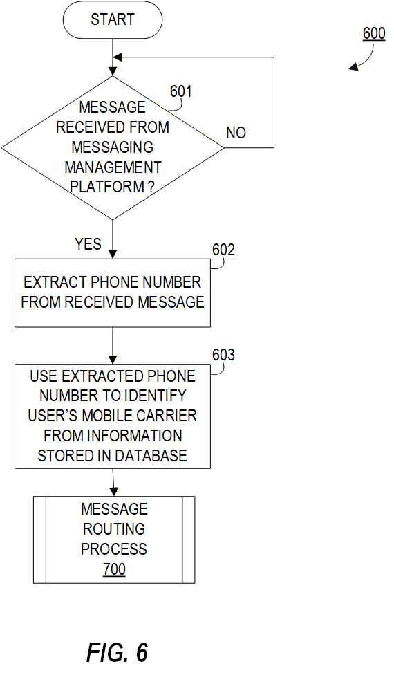
Figure 7.1 — Example of reference numbers identifying parts in a utility figure.
Required:
- Every part or element mentioned in the written description must have a reference number in the drawings.
- Every component shown in the drawings must be mentioned in the description.
This reciprocal requirement ensures that the figures and the specification consistently describe the same invention.
2. Unique Numbers for Unique Parts
Rules:
- One reference number = one part.
- Do not reuse the same number for different components.
- Identical parts (e.g., bolts, pins, bearings) may share one number if they are not discussed individually.
- If identical parts must be distinguished, assign separate numbers.
3. Same Part → Same Number Across All Figures
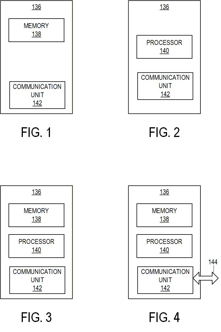
Figure 7.3 — The same part must carry the same number in every figure in which it appears.
If a part appears in multiple figures:
- It must always use the same reference number.
- Numbers must remain stable from FIG. 1 to the final figure.
Changing numbers between figures is a common examiner objection.
4. Reference Letters (When Allowed)
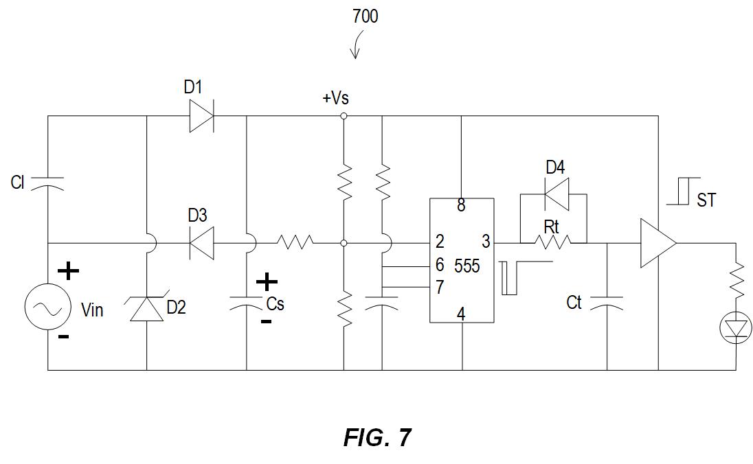
Figure 7.4 — Letters may be used for non-physical elements or customary electronics notation.
Reference letters may be used when:
- identifying intangible elements (e.g., A = airflow, B = magnetic flux)
- using standard electrical symbols such as:
- R1, R2… for resistors
- C1, C2… for capacitors
- Q1… for transistors
- IC5 for integrated circuits
Letters must be from the English alphabet.
5. Lettering Style and Readability
Reference numbers and letters must:
- use a simple, readable font
- be non-italic and non-script
- match the clarity and thickness of the drawing style
6. Minimum Text Height Requirements
Reference numbers and letters must be:
- at least 3.2 mm (⅛") or ~11 pt high
- superscripts/subscripts may be smaller
- still must be readable without magnification
Optional rule for descriptive labels
If descriptive text appears in figures, it must also comply with minimum height rules.
To avoid overly tall uppercase letters, use ALL CAPS for short labels to control height.
7. Placement of Reference Numbers
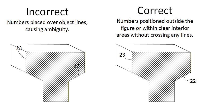
Figure 7.7 — Correct placement of reference numbers. Left: incorrect—numbers placed over object lines, causing ambiguity. Right: correct—numbers positioned outside the figure or within clear interior areas without crossing any lines.
Rules:
- Place each numeral close to the part it identifies.
- Keep numerals far enough from other parts to avoid ambiguity.
- Avoid placing numbers too far away unless absolutely necessary.
Preferably outside the figure
To prevent clutter:
- place reference numbers outside the object outline
Never place numerals across lines
Reference numbers must not cross:
- object lines
- edge lines
- hidden lines
- hatch lines
Crossing lines is a USPTO error that will result in an objection.
8. Replacing Lead Lines With Underlines
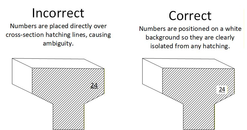
Figure 7.8 — Correct placement of reference numbers on a surface or cross-section. Left: incorrect—numbers are placed directly over cross-section hatching lines, causing ambiguity. Right: correct—numbers are positioned on a white background so they are clearly isolated from any hatching.
A lead line may be replaced with an underline when the reference number sits directly on the surface or cross-section it identifies.
Rules:
- Underlining may be used when the reference number lies on the surface of the part it designates.
- Hatching must be interrupted under the number when used inside a cross-section.
- This method is useful when space is limited.
- Because underlined numbers may be confused with object edges, use this technique sparingly.
Summary
Reference numbers are essential for linking the written description to the figures. To comply with USPTO and PCT standards:
- Every part mentioned in the description must be numbered in the drawings
- Every numbered part must appear in the description
- Numbers must be unique and consistent across all figures
- Letters may be used for intangible elements or electronics
- Minimum text height: 3.2 mm (⅛″)
- Place numbers close to the part, without crossing lines
- Use clear, simple lettering
Following these rules ensures clarity and prevents examiner objections related to figure labeling.