Lead Line Standards
Lead lines are essential for connecting reference numbers to the parts they identify in utility patent drawings. Proper lead line usage ensures clarity, prevents ambiguity, and keeps drawings compliant with USPTO and PCT standards. This chapter outlines all required rules for lead lines, including placement, usage exceptions, arrow rules, and restrictions.
1. Basic Requirements for Lead Lines
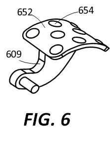
Figure 8.1 — Lead line placed between a reference numeral and the part it designates.
A lead line must:
- extend between each reference number and the corresponding part
- touch the part directly
- stop just short of the reference number (never touching it)
- be positioned to avoid confusion with other parts or lines
- be drawn using simple, clean strokes, consistent with drawing line weight standards
Lead lines help maintain clarity—especially when figures become crowded with multiple components.
2. Lead Lines Must Not Connect Separate Figures
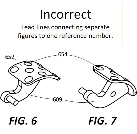
Figure 8.2 — Lead lines may not span across separate figures.
If an identical part appears in more than one figure:
- Each figure must have its own lead line to its own numeral, even if the number is the same.
- Lead lines must never cross figure boundaries.
- A single numeral cannot be shared by two figures via two branching lead lines.
This rule prevents misinterpretation and preserves the independence of each figure.
3. Using Arrows With Lead Lines
Figure 8.3 — Arrow used to designate a group of elements with a single reference numeral.
Arrows may be used to designate a group of parts with a single reference number:
- one reference number may be used to label the group
- an arrow on the lead line points in the general direction of the group
- individual items may still have their own numerals if required
Arrows should not touch the part; they point towards the group.
4. Lead Line Placement and Clarity Requirements
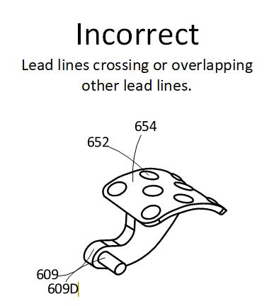
Figure 8.4 — Lead lines should avoid crossing other lines whenever possible.
Lead lines must:
- not cross other lead lines
- not overlap or merge with other lines
- be long enough to clearly point to the specific component
- be short enough to avoid clutter
- cross object lines only at a sharp angle, making it clear the line is a lead line and not part of the structure
- not point to blank areas or ambiguous regions
Following these rules prevents USPTO objections related to clarity, ambiguity, and figure readability.
Summary
Lead lines are one of the most scrutinized components of utility patent drawings. To comply with USPTO and PCT standards:
- Every reference numeral must connect to the part it identifies
- Lead lines may be replaced with underlines only in limited space-constrained situations
- Lead lines must never connect between separate figures
- Arrows may designate groups of parts, but must not be confused with movement arrows
- Placement must avoid line confusion and visual clutter
By following these standards, your drawings remain clear, precise, and fully compliant with USPTO expectations.