Line Standards
Utility patent drawings must be created using clear, consistent, and reproducible line work. Since USPTO examiners routinely photocopy, scan, and reduce drawings, the lines must remain sharp and readable under all conditions. This chapter summarizes the required line types, roles, and thicknesses, with examples similar to standard drafting practice.
Character of Lines
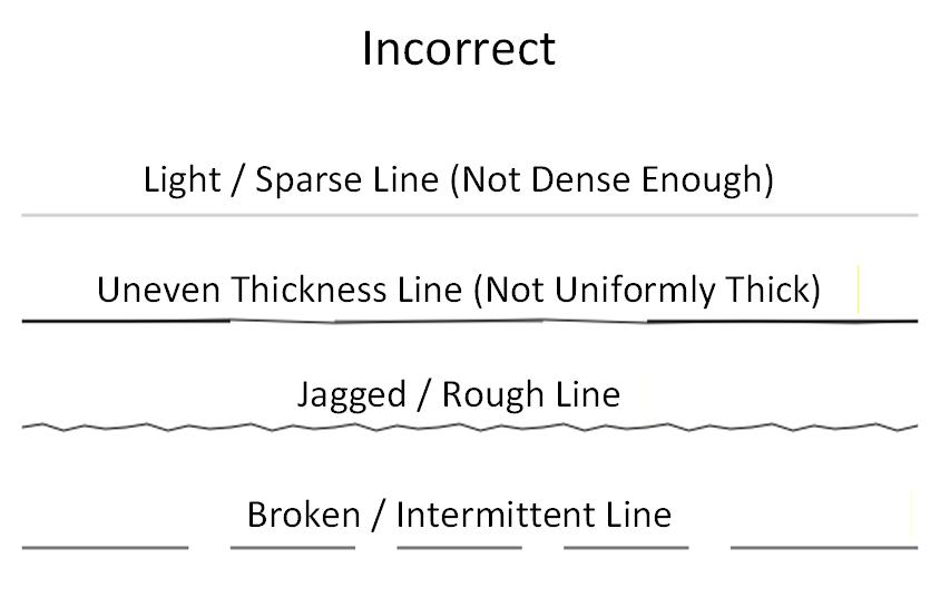
Figure 11.1 — All patent drawings must use solid black, uniformly thick lines with smooth edges.
Except for photographs and approved color drawings:
- All artwork must be drawn using black lines only.
- Lines must be uniform, solid, sharp, and smooth.
- No pixelation, gradients, antialiasing artifacts, or inconsistent weights are permitted.
- Lines must be thick enough to reproduce cleanly when reduced or photocopied.
This foundation ensures that every part of the invention remains legible under examination and during long-term archival.
Line Types and Widths
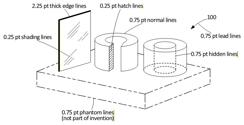
Figure 11.2 — Typical line types and widths used in utility patent drawings.
The USPTO recognizes several distinct line types, each serving a technical purpose.
1. Edge Lines (Object Outlines)
- Type: continuous
- Thickness: ~0.75 pt
- Represent visible edges, boundaries, and contours of the invention.
- Must be clear and consistent across all figures.
2. Hidden Lines (Obscured Edges)
- Type: dashed
- Thickness: ~0.75 pt
- Used only when necessary to show structure hidden behind another part.
- Excessive hidden lines may clutter the figure and should be avoided unless required for understanding.
3. Phantom Lines (Non-invention or Moved Positions)
- Type: dot–dot–dash
- Thickness: ~0.75 pt
- Used to depict:
- elements not part of the claimed invention, or
- a moved/alternate position of a component
- For clarity, non-invention elements may alternatively be shown in continuous lines.
4. Shading Lines (Surface Contour)
- Type: continuous or irregularly broken
- Thickness: ~0.25 pt
- Indicate surface shape or light orientation.
- Must be thin enough not to be confused with object edges.
5. Thick Edge Lines (Thick Materials)
- Type: continuous
- Thickness: ~2.25 pt
- Used for:
- thick sheet materials
- cables or cords
- parts too thick for a normal 0.75 pt edge line
- Should be used sparingly and consistently.
6. Hatch Lines (Sectional Views)
- Type: continuous, diagonal
- Thickness: ~0.25 pt
- Used only for cut-away surfaces in sectional views.
- Must be thinner than edge lines to avoid confusion.
7. Lead Lines
- Type: continuous (or matching the line type of the part)
- Thickness: 0.75 pt
- One end must touch the component.
- The other end must stop just short of the reference number or letter.
- Must never cross object lines, hatch lines, or clutter the figure.
Additional Standards and Best Practices
Avoid Excessively Thick Lines
- Lines above ~0.75 pt (except thick edge lines) will cause:
- merging of fine details
- loss of small clearances
- crowding between adjacent lines
When Thicker Lines Are Acceptable
- Sectional view edge lines may be up to ~1.0 pt to differentiate them from 0.25 pt hatching.
- Thick cords, walls, or edges may be represented by ~2.25 pt lines when a pair of parallel lines would be excessive.
Summary
- Solid black lines only; no color except for approved photographs.
- Uniform, sharp, smooth linework is mandatory.
- Main edges: continuous, ~0.2 mm
- Hidden edges: dashed, ~0.2 mm
- Phantom / moved positions: dot–dot–dash, ~0.2 mm
- Shading & hatching: ~0.1 mm
- Thick edges: ~0.5–0.8 mm
- Lead lines: 0.1–0.2 mm, drawn cleanly
- Avoid clutter, merging lines, or excessively heavy edges.
- Maintain line consistency across all figures in the application.
Consistent line standards are essential for creating legally compliant, readable, and professional utility patent drawings.